
Thanks — glad you asked. At Thesun Industry we treat side milling not as a routine operation but as a precision capability that often determines whether a component meets fit, form, and function in the field. Below is a professional, manufacturer-level guide to side milling: what it is, how it works, the equipment and parameters that matter, materials and tooling choices, typical applications, common problems, and proven remedies. If you’d like, our factory can run a DFM review or provide test cuts under our one-stop service to validate your design — just send a CAD file and we’ll take it from there.
What is side milling?
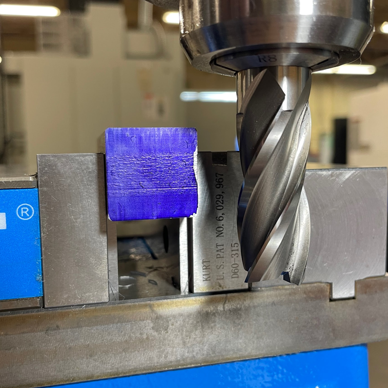
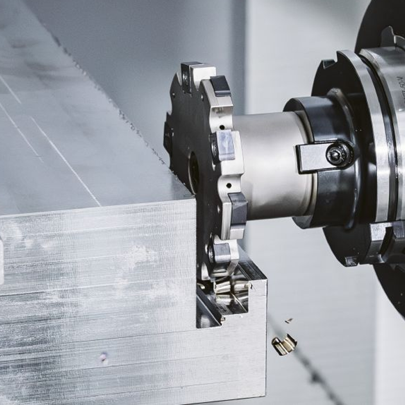
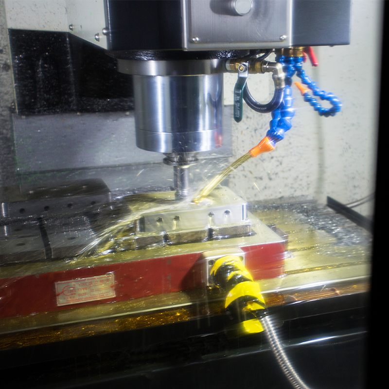
Side milling is a milling operation in which the cutting action comes from the peripheral (side) teeth of the cutter rather than only the face. Typical side-milling cutters include end mills and side mills where the cutter’s lateral edges remove material to produce vertical walls, shoulders, grooves, chamfers, and profiles. In CNC practice side milling is a core method for producing precise, straight or contoured walls and for finishing features that require tight dimensional control and a good surface finish.
How side milling works — the basic steps
- Fixturing and workpiece setup. A rigid, stable setup is essential. The part is clamped so the milled wall references a fixed datum and resists lateral cutting forces.
- Tool selection and positioning. Choose a cutter with the proper diameter, flute count, and corner geometry. Position the cutter for the intended radial and axial engagement.
- Radial engagement (RDOC). This is the percentage of tool diameter engaged laterally. RDOC controls chip load per tooth and lateral force.
- Axial depth of cut (ADOC). The axial or vertical depth removed per pass; it affects heat generation and tool life.
- Toolpath execution. The CNC follows programmed paths (straight, contour, climb or conventional milling, dynamic milling). Effective chip evacuation and dwell locations are planned.
- Finishing pass. A light finishing pass optimizes surface finish and dimensional accuracy.
Machines, tooling, and fixturing
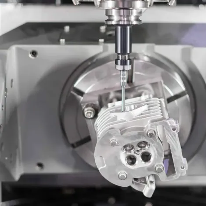
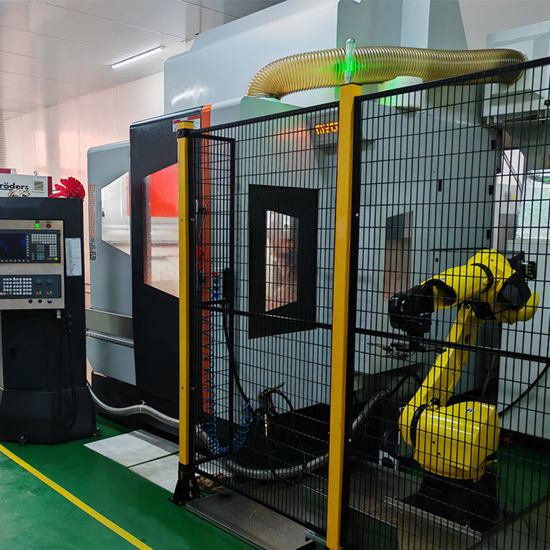
- CNC machines: Vertical mills, horizontal mills, and multi-axis machining centers are all used for side milling. Machine rigidity and spindle taper quality are critical for repeatability.
- Tooling: End mills (square, corner-radius, ball) are the most common. For heavy radial cuts use reduced-runout holders: shrink fit, hydraulic chucks, or high-precision collets. Multi-flute cutters improve productivity but increase required spindle horsepower.
- Fixtures: Vises with soft jaws, modular clamps, vacuum fixtures for thin parts, and dedicated custom workholding for odd geometries. Proper fixturing reduces vibration and improves surface finish.
- Coolant and chip control: Flood coolant or high-pressure coolant (HPC) for stainless/titanium; air blasts or MQL for aluminum and plastics. Chip conveyors and proper flute geometry aid evacuation.
Material considerations and tool choices
Different materials demand different strategies:
- Aluminum (6061, 7075): High RPM, moderate feed, polished flute tools, and aggressive chip evacuation. Use Al-specific coatings and polished flutes to avoid built-up edge.
- Carbon/alloy steels (1018, 4140): Slower speeds, rigid setup, CVD/TiN coated carbide, use coolant to control heat.
- Stainless steel (304, 316): Work hardening risk — use sharp HSS or coated carbide, high-pressure coolant, reduced radial engagement and multiple light passes.
- Titanium / Inconel: Low thermal conductivity — very shallow cuts, stiff tooling, and ample coolant.
- Brass/Copper: Soft, can smudge — sharp tools and lower cutting temperatures.
- Plastics/composites: Low forces but risk of melting or delamination — sharp tools, high surface speeds for plastics, diamond tooling for CFRP.
Key cutting parameters (what you must control)
- Spindle speed (RPM) and cutting speed (SFM or m/min) determine surface speed at the cutter face.
- Feed rate (IPM or mm/min) and chip load per tooth control material removal rate and chip thickness.
- RDOC (radial depth) influences lateral force — reduce RDOC to limit chatter.
- ADOC (axial depth) affects heat and tool wear — prefer multiple shallow axial passes for tough alloys.
- Tool engagement angle and helix — these affect harmonic responses and chip formation.
- Toolholder runout — keep minimal to avoid uneven wear and poor finish.
Toolpath strategies and best practices
- Climb milling is generally preferred for better surface finish and longer tool life where machine rigidity and backlash control allow.
- Dynamic (trochoidal) milling reduces instantaneous radial engagement and is excellent for slotting and heavy axial/low radial cuts.
- Contour and plunge strategies: use trochoidal for roughing, then finish with a constant-step side pass for walls.
- Multiple light passes produce superior finishes and reduce deflection.
Advantages and limitations
Advantages
- High dimensional accuracy for vertical walls and steps.
- Excellent surface finish when optimized.
- Versatile across materials and part sizes.
- Suitable for both roughing and finishing.
Limitations
- Generates high lateral forces — needs stiffness and proper fixturing.
- Longer tools or deep walls risk deflection and chatter.
- Chip evacuation can be challenging in deep slots and narrow channels.
- Burr formation on ductile materials requires secondary deburring.
Common problems and practical remedies
- Chatter / vibration: Increase rigidity, shorten tool overhang, reduce RDOC, adjust spindle speed to avoid resonance, or add damping (vibration-damping holders).
- Tool deflection: Use larger diameter or stiffer tools, lower feed per tooth, or reduce ADOC; add intermediate support fixtures for long shafts.
- Poor chip evacuation: Use tools with polished flutes, increase axial and radial clearance, run higher coolant pressure, or use peck-style step-out passes.
- Heat and work hardening: Reduce cutting speed, increase coolant, switch to sharper geometry or fewer flutes.
- Burrs: Optimize exit strategies, add chamfer or edge breaks in CAM, or plan for secondary deburring operations.
Applications and industry use
Side milling is used widely across sectors:
- Automotive: gear housings, bracket vertical walls, feature finishing.
- Aerospace: precision mating surfaces, stiffener walls in structural components.
- Mold & die: cavity walls, parting surfaces, inserts.
- Medical & precision instruments: vertical bores and high-tolerance profiles.
- General fabrication: control panels, enclosures, fixtures.
Quality control and process validation
At Thesun Industry we integrate in-process checks and post-process inspection into every side-milling operation. Typical validation steps include: first-part inspection (CMM or optical), in-cycle micrometer checks, surface roughness testing (Ra/Rz), and a final functional inspection before parts move to plating or assembly. When we supply parts we include traceable inspection reports and process parameter logs as part of our custom service.
Closing — how Thesun Industry can help
If side milling is a critical operation for your part, partner with a manufacturer that treats process engineering as a core competency. Thesun Industry offers a one-stop service from CAM validation and test cuts through mass production, combining stamping, CNC, and automated assembly to deliver ready-to-install components. We work with tier-1 suppliers and can provide material sourcing, fixture design, DFM optimization, and custom service contracts to meet your schedule and quality goals.
Ready to validate your design or get a quotation? Send your CAD model and tolerancing notes — our engineering team at Thesun Industry will run a free manufacturability review and propose an optimized machining strategy tuned to your materials, volume, and cost targets.